TeleScience History
v0.1
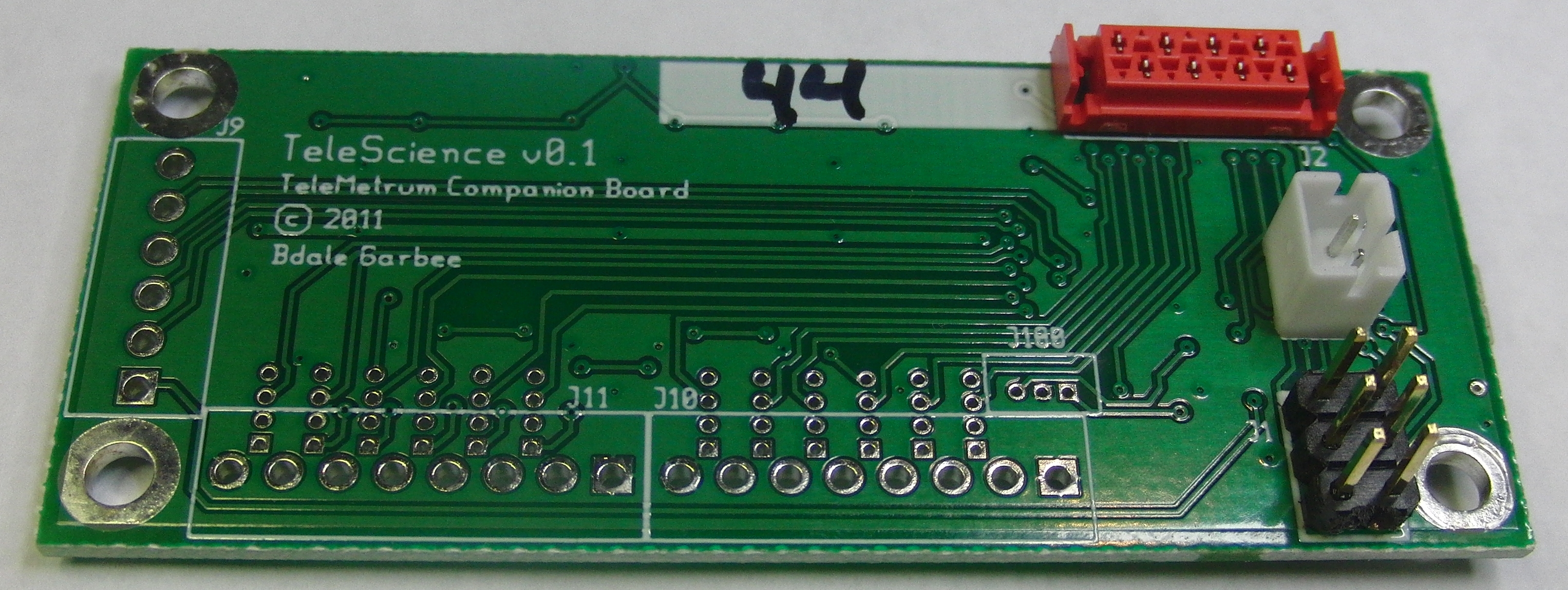
This is a photo of our original TeleScience board with 12 analog inputs, all of which could be used for thermistors... and 5 general-purpose I/O pins. This board could also be used standalone as a USB I/O device.
Motivation
Bdale's son Robert got interested in mapping the temperatures experienced by nose cones and fins in flights beyond Mach 1, and we started working with our good friend Jeff Lane from Shockwave Rocketry to instrument one or more of his nose cones in pursuit of that goal.
6 v0.1 prototypes were built, of which 2 were installed in 2YikStik and flown at LDRS 30 in early September 2011. Unfortunately, we experienced a mechanical failure in the airframe before going fast enough to get exciting data, but post-flight analysis suggested the TeleScience boards were working fine up until "the incident". A replacement airframe YikStik3 flew successfully at Airfest 18 in September 2012.
From the beginning, it was easy for us to imagine other experiments that would be facilitated by having generic analog data inputs and a few control lines. But experience using the v0.1 boards made it clear that we'd designed something that was "too specific" to the primary objective of measuring temperature rises on a high-speed airframe. This is why v0.1 has been abandoned in favor of a significantly re-designed v0.2.
Features
User View
- Small circuit board mounted near TeleMetrum
- Requires TeleMetrum v0.2 or later, as v0.1 does not have the required companion board interface
- 12 analog input channels, each of which can independently be configured for an NTC thermistor or generic 0-3.3 volt analog input.
- 5 general purpose I/O lines
- On-board flash memory for data logging.
- USB interface for programming and development
Developer View
- Hardware Features
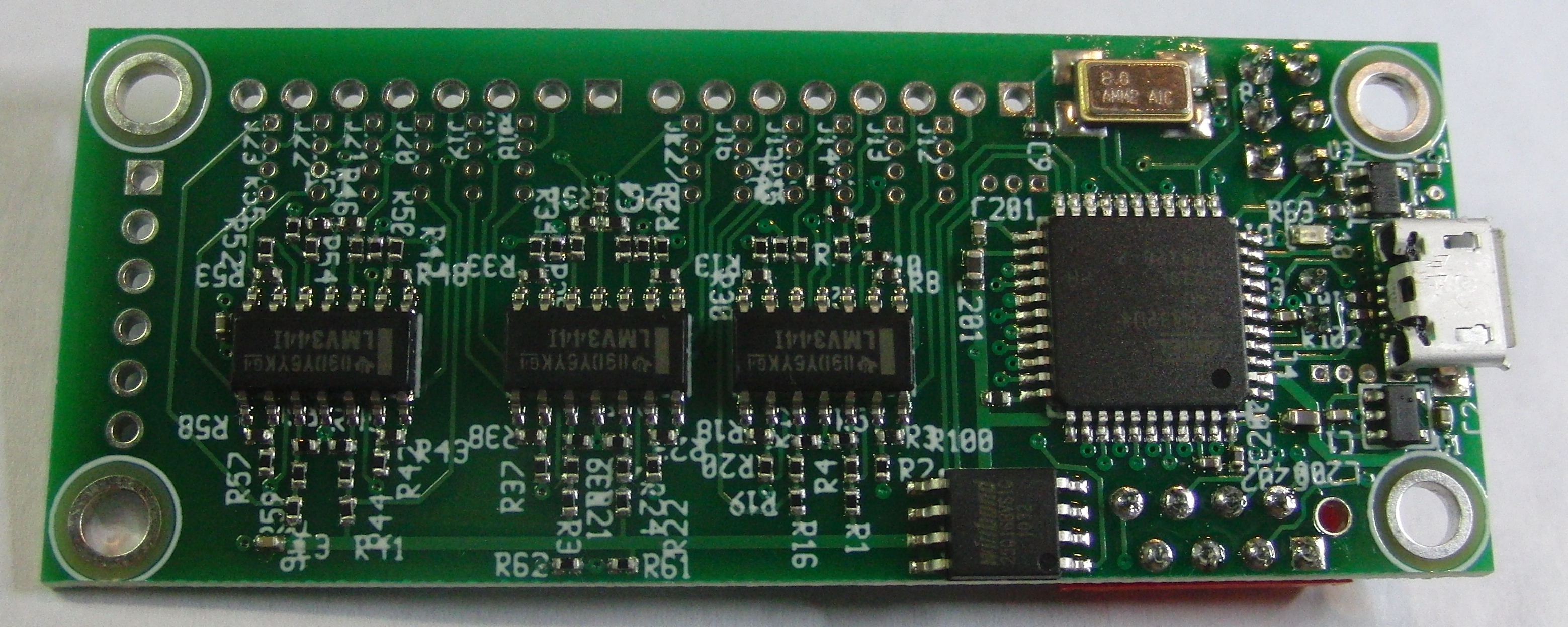
- Atmel ATmega32U4 Microcontroller
- 32k Flash
- 2.5k + 832 bytes SRAM
- 1k EEPROM
- 12-channel 10-bit ADC
- SPI target interface
- USB interface which can be used for programming
- In-system programming interface
- Winbond W25Q16 serial flash memory
- 2M x 8
- SPI interface
- Atmel ATmega32U4 Microcontroller
- Software Features (planned)
- programmed in C using gcc-avr
- Runs from on-chip flash, uses on-chip RAM
- Tools Used
- gEDA for schematic capture and PCB layout
- Licenses
- The hardware is licensed under the TAPR Open Hardware License
- The software is licensed GPL version 2
Artifacts
The schematic and PC board design for v0.1 exist on git.gag.com in the v0.1 branch of project hw/telescience.