TeleMetrum History
The v0 and v1 series have a lot of common hardware features. The final version in this line, v1.2 looked like:
User View
- Recording altimeter for model rocketry
- Supports dual deployment (can fire 2 ejection charges)
- 70cm ham-band transceiver for telemetry downlink
- Barometric pressure sensor good to 45k feet MSL
- 1-axis 70-g accelerometer for motor characterization
- On-board, integrated GPS receiver
- On-board non-volatile memory for flight data storage
- USB for power, configuration, and data recovery
- Integrated support for LiPo rechargeable batteries
- Uses LiPo to fire e-matches, can be factory modified to support separate pyro battery
- 2.75 x 1 inch board designed to fit inside 29mm airframe coupler tube
Developer View
- Hardware Features
- TI CC1111F32 Low Power RF System-on-Chip
- Sub-1Ghz transceiver
- 8051 MCU
- 32k Flash
- 4k RAM
- USB 2.0
- 6 12-bit analog inputs (11 bits with single-ended sensors)
- 2 channels of serial I/O
- digital I/O
- Winbond W25Q16 serial flash memory
- 2M x 8
- SPI interface
- SkyTraq Venus634FLPx GPS receiver
- on-board Taoglas AP.17A.01 single-stage active patch antenna
- U.FL connector with 3.3V DC can be re-purposed for optional external amplified antennas
- async serial interface
- Freescale MP3H6115A pressure sensor
- Analog Devices ADXL78 70g accelerometer.
- TI CC1111F32 Low Power RF System-on-Chip
- Software Features
- Written mostly in C with some 8051 assembler
- Runs from on-chip flash, uses on-chip RAM, stores flight data to serial DataFlash chip
- USB serial emulation for "console" interface
- Tools Used
v0.1
This is a photo of our original board with serial port for off-board GPS, without the big off-board 1000uF cap from the original ejection circuit. All v0.1 boards were hand-assembled by Bdale. This is more significant than it sounds... the CC1111F32 is a 36-pin QFN package, which necessitates reflow soldering. Since we needed to reflow solder anyway, and because TI used them in their reference design, we went a little crazy and used 0402 passive parts everywhere. That means working under a microscope to place parts! Without an inspection microscope, hand loading and testing might be impossible.
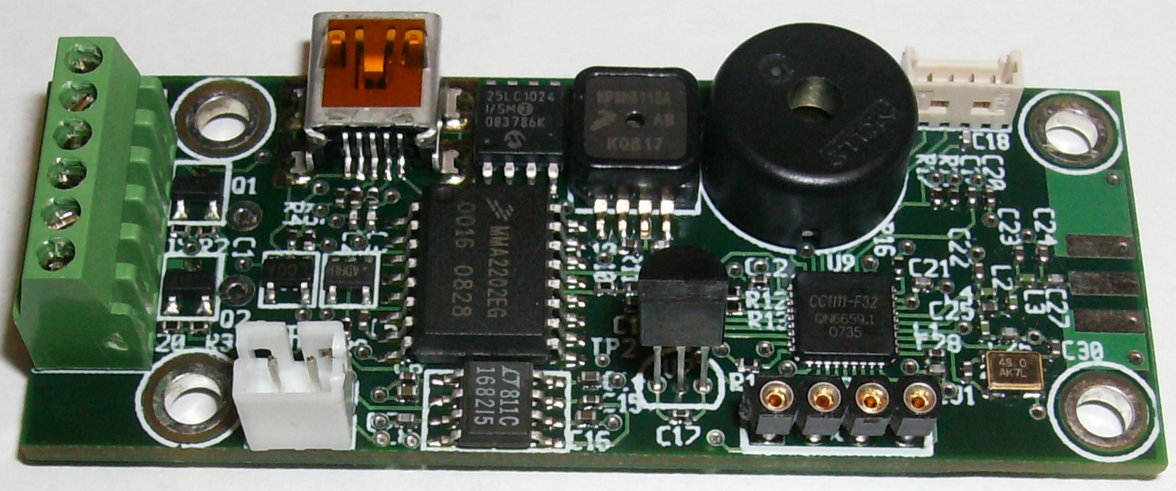
The v0.1 board was significantly different than later versions, in both mechanical and circuit terms.
- 2.5 x 1 inch board with all parts mounted on one side
- 4-pin PicoBlade serial port connector for attachment of external GPS module
- USB connector projected approximately 3mm over the edge of the board
- Debug connector used 4 IC socket pins on 100 mil centers
- 50ma LDO regulator on early boards, later boards used a 100ma part
- Microchip 25LC1024 CMOS serial EEPROM instead of DataFlash
- 128k x 8
- SPI interface
- Microchip MCP9700A discrete temperature sensor
- used 1000uF electrolytic capacitor charged to 5V for pyro supply
- a dual LED instead of just one attached to the CPU
The v0.1 artwork had three issues, two of which required physical rework on each board, all of which were fixed in v0.2.
- The USB connector footprint was placed wrong, so that the connector hung out over the edge of the board instead of being flush.
- We needed chip select on the SPI memory. To fix that, we gave up the ability to put the accelerometer into self-test mode and used that GPIO line to pull chip select on the memory, which required two cuts and two jumpers.
- The igniter sense circuits each needed a second resistor to complete the voltage divider so our 3.3V CPU ADC could read the 5V ejection voltage. This was fixed by changing two resistor values, and tacking two additional resistors onto the board with jumpers to ground.
The schematics and PCB artwork for this version as of the working-v0.1 tag are available here as pdf copies for easy reference:
v0.2
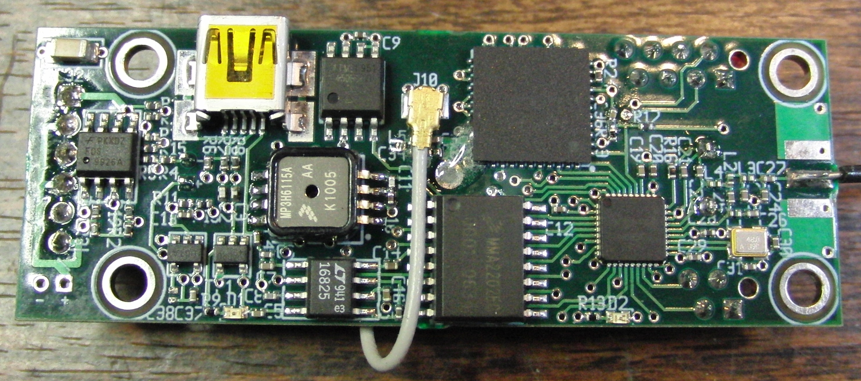
These are photos of our second version. All v0.2 boards were hand assembled by Bdale. The board featured in these photos also used the Tyco header for pyro connections that we used to offer as an option. Nobody ever bought a board with anything but screw terminals, so we no longer offer this option.
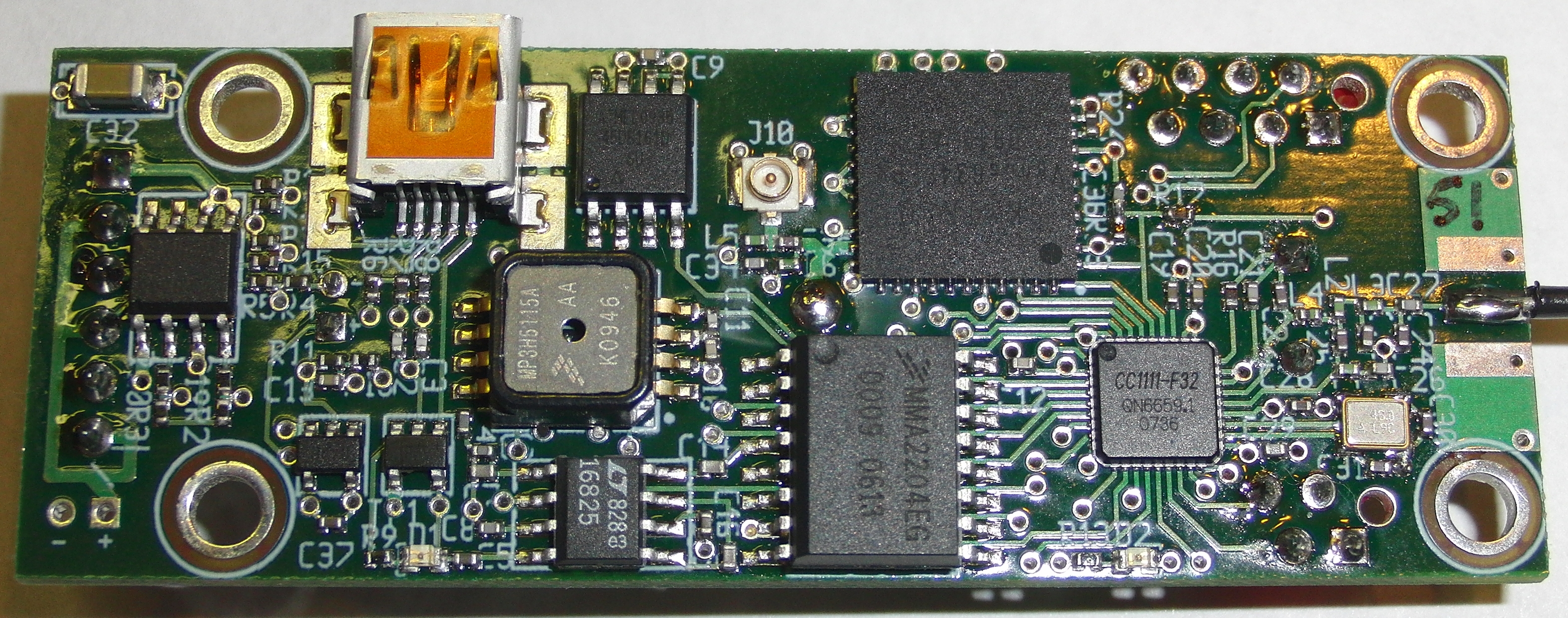
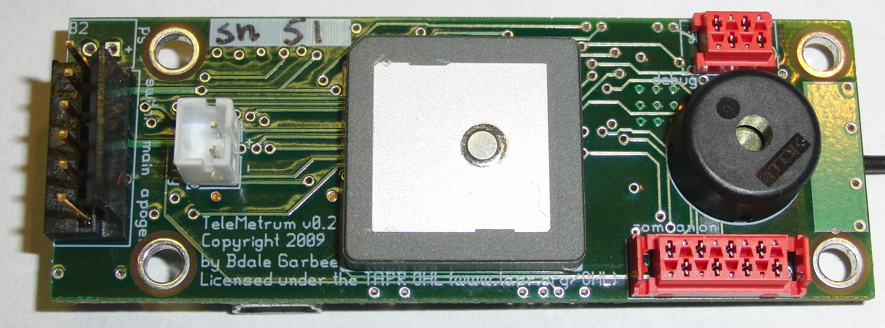
Lots of things were different from v0.1. Perhaps the biggest change was integrating a Venus GPS receiver and a passive patch GPS antenna. This required stretching the board length to 2.75 inches, and changing the layout to put through-hole parts on the opposite side from the surface mount parts. While we were at it, things were rearranged to put tall parts near the center and not on the board edges so that boards could be mounted in smaller diameter tubes.
Another significant change was adding a "companion" port, intended to support expansion boards but also possible to use as a programming interface. With a suitable cable, the presence of the companion port allowed any TeleMetrum board to be used to re-program any other TeleMetrum or TeleDongle board. Elimination of the discrete temperature sensor and second LED were necessary to free up the pins needed for the companion interface.
We also changed to a different flash memory chip with 1 megabyte of storage.
Issues with the v0.2 boards included:
- The passive GPS antenna turned out to have disappointing performance due to our many PCB geometry constraints.
- The initial voltage regulator on v0.2 boards was a 100mA part. Once we realized how much power the GPS receiver needed to achieve initial lock, we switched to a 150mA part.
- With the LiPo battery charging rate from USB set at approximately 100mA, total power consumption can exceed the rate at which we draw power from the USB interface, particularly when the GPS is in cold start mode. This means a battery must be attached during operation, and also that the battery will only charge effectively from USB when the board is turned off.
- The reset circuit worked well for the cc1111 but was marginal for the GPS chip .. sometimes the board would have to be power cycled several times to get the GPS to come up correctly.
The schematics and PCB artwork for this version are on the v0.2 branch in our git repository, here are pdf copies for easy reference:
v1.0
These are photos of our third version, which was our first production build. By the time we understood what we wanted to change in v0.2, things worked well enough that every time we went to a launch someone would ask about buying boards from us. So in January 2010, Keith and Bdale made the decision to produce enough boards to sell some to others. These were sold between April and December 2010, and performed very well.
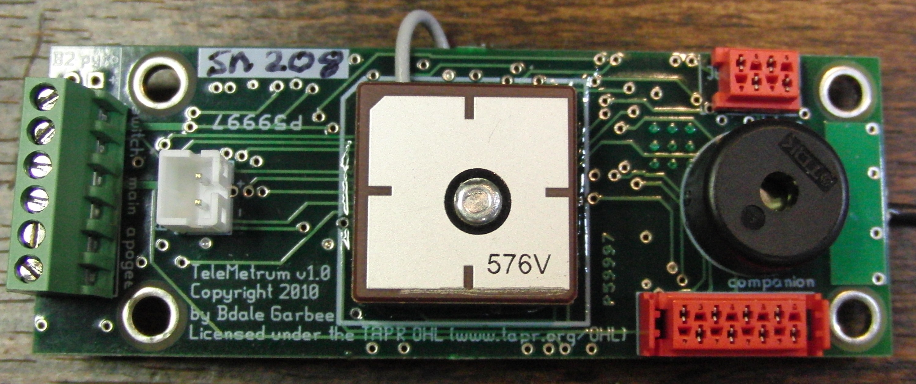
The changes from v0.2 were fairly small. The value of the reset capacitor changed to increase the probability of the GPS chip coming up correctly, and we moved to using a Taoglas amplified patch antenna attached to the U.FL connector instead of the passive GPS patch antennas.
There were really only two issues with the v1.0 boards that annoyed us. The first was that the reset circuit still wasn't satisfying. The GPS chip would sometimes fail to initialize, particularly in hot weather. The second was that fluctuation of the 3.3 volt power rail correlated with radio transmission induced noise patterns in the accelerometer data.
The schematics and PCB artwork for this version are on the v1.0 branch in our git repository, here are pdf copies for easy reference:
v1.1
These are photos of v1.1, which rightfully looks very similar to v1.0. These boards were sold through most of 2011.


There were several changes in v1.1:
- different flash memory part due to supplier availability problems. It turned out that 2 megabyte chips were cheaper than 1 megabyte, so the size doubled.
- updated reset circuit to improve reliability at temperature extremes
- changed the GPS antenna footprint to eliminate the large through-hole originally intended for use with a passive patch
- irq line eliminated from the companion port
- an additional resistor divider added to allow sampling the 5V supply
With an associated software change, being able to sample the 5V and 3.3V rails made it possible to factor out almost all of the coherent noise from the accelerometer data seen with v1.0 boards.
The one big problem with v1.1 boards turned out to be that they would sometimes reset during flight, usually when firing pyro charges. Bdale wrote a blog entry that explains in some detail what we finally learned was causing this.
For those who don't have ready access to the gEDA suite, here are pdf snapshots of the files for Production PCB version 1.1 in more easily readable form.
v1.2
This is our last production version of the 1.0 series, first made available for sale on Christmas day 2011.
Changes from v1.1 include:
- changed to 70g accelerometer from Analog Devices since Freescale MEMS parts are still unavailable following the Japanese earthquake and tsunami.
- reset controller changed from 3.15 to 3.00 volt trip point
- bypass cap added to LDO input
- pyro circuit resistor values tweaked to eliminate a glitch that at least in theory made it possible for pyro charges to fire at power on. We never saw a problem, but the change was easy and obvious.
v2.0
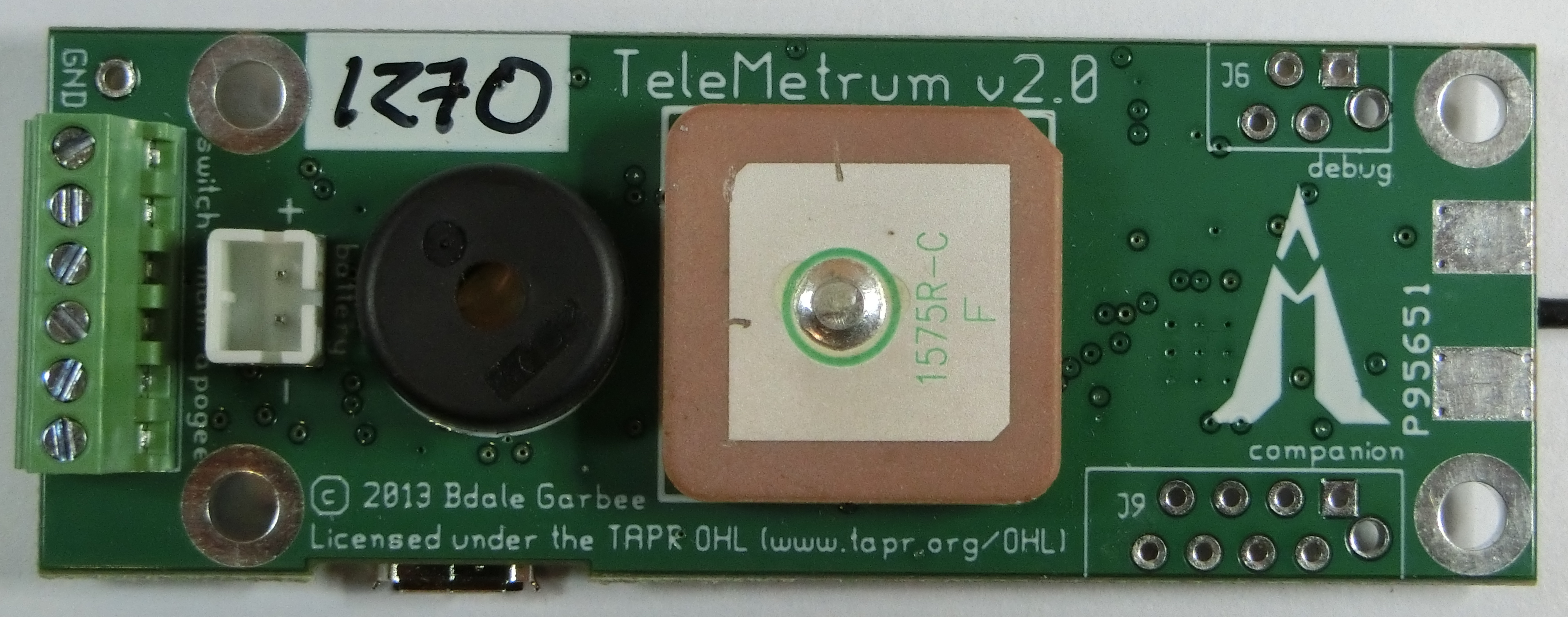
Prototypes of v2.0 were first flown at Airfest 2013, and v2.0 was sold through fall of 2019.
Compared with the v1 series, v2 includes a better GPS (uBlox vs Skytraq), higher power radio (40mW instead of 10mW), wider range and more precise pressure sensor (100k' MSL vs 45k' MSL), larger on-board storage (8MB vs 2MB), more precise, wider range accelerometer (12 bits instead of 10 bits, 105g instead of 70g) and faster processor (32-bit ARM Cortex M3 instead of 8-bit 8051).
User View
- Recording altimeter for model rocketry
- Supports dual deployment (can fire 2 ejection charges)
- 70cm ham-band transceiver for telemetry downlink
- Barometric pressure sensor good to 100k feet MSL
- 1-axis 105-g accelerometer for motor characterization
- On-board, integrated GPS receiver
- On-board non-volatile memory for flight data storage
- USB for power, configuration, and data recovery
- Integrated support for LiPo rechargeable batteries
- Uses LiPo to fire e-matches, can be made to support separate pyro battery
- 2.75 x 1 inch board designed to fit inside 29mm airframe coupler tube
Developer View
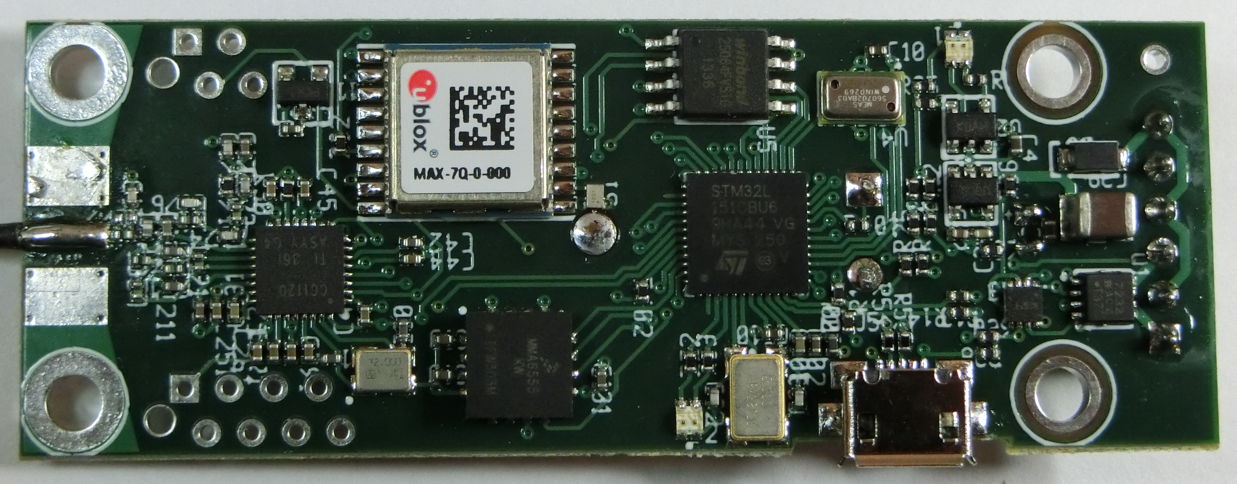
- Hardware Features of v2.0
- ST Micros STM32L151 ARM Cortex M3 based Microcontroller
- TI CC1120 High Performance RF Transceiver for Narrowband Systems
- 150mA 3.3V LDO regulator
- Winbond W25Q64CV serial flash memory
- u-blox MAX-7Q GPS receiver
- on-board passive patch antenna
- async serial interface
- Measurement Specialties MS5607 Micro Altimeter Module
- Wide range — 120kPa to 1kPa (approximately -1500m to 31000m)
- High precision — 2.4Pa resolution (approximately 20cm at sea level)
- Factory calibrated.
- Freescale MMA6555 Single Axis SPI Intertial Sensor
- +- 105g full-scale
- on-chip 12-bit digitizer
- Software Features
- Written mostly in C with some ARM assembler
- Runs from on-chip flash, uses on-chip RAM, stores flight data to serial flash
- USB serial emulation for "console" interface
- Tools Used
- gEDA for schematic capture and PCB layout
- Licenses
- The hardware is licensed under the TAPR Open Hardware License
- The software is licensed GPL version 2
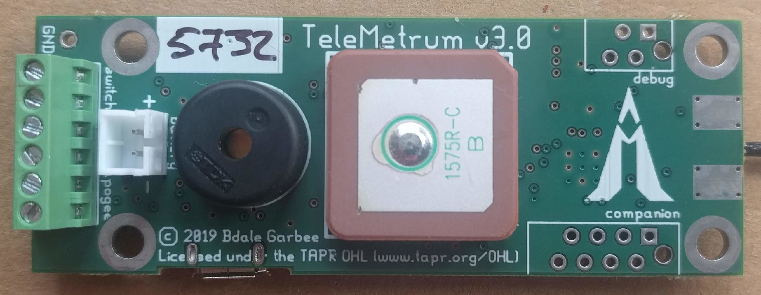
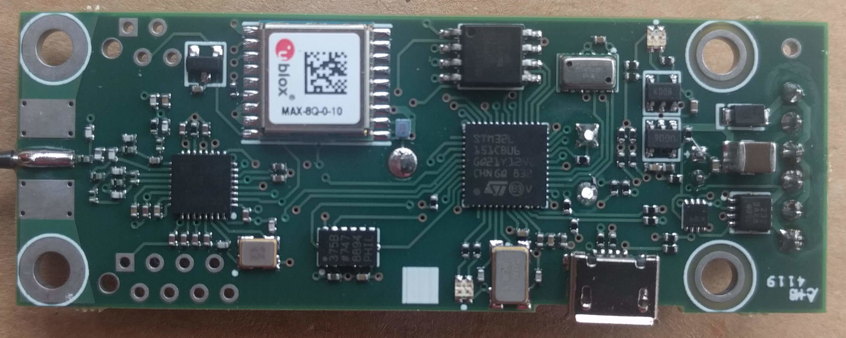
v3.0
These are photos of version 3.0:
Developer View
- Hardware Features of v3.0
- ST Micros STM32L151 ARM Cortex M3 based Microcontroller
- TI CC1200 Low Power, High Performance RF Transceiver
- 150mA 3.3V LDO regulator
- Winbond W25Q64CV serial flash memory
- u-blox MAX-8Q GPS receiver
- on-board passive patch antenna
- async serial interface
- Measurement Specialties MS5607 Micro Altimeter Module
- Wide range — 120kPa to 1kPa (approximately -1500m to 31000m)
- High precision — 2.4Pa resolution (approximately 20cm at sea level)
- Factory calibrated.
- Analog Devices ADXL375 3-Axis Digital MEMS Accelerometer
- +- 200g full-scale
- on-chip digitizer
- Software Features
- Written mostly in C with some ARM assembler
- Runs from on-chip flash, uses on-chip RAM, stores flight data to serial flash
- USB serial emulation for "console" interface
- Tools Used
- Lepton EDA for schematic capture
- pcb-rnd for PCB layout
- Licenses
- The hardware is licensed under the TAPR Open Hardware License
- The software is licensed GPL version 2
Compared with v2 series, v3 includes a better GPS (uBlox v8 vs v7), the TI CC1200 radio used in our other products instead of the CC1120 used only in TeleMetrum v2 (more or less the same performance, but one less device driver for us to have to worry about!), and more accelerometer range with approximately the same precision.
This board was designed using lepton-eda and pcb-rnd.
Here are pdf snapshots of the design for Production PCB version 3.0, along with a bill of materials: